
4.3
Owner's of the ADC Clothes Dryer AD-310 gave it a score of 4.3 out of 5. Here's how the scores stacked up:
89
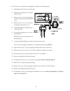
Input #12 is the heat on status. It is used to monitor the Phase 5 microprocessor controller
(computer) heat output. Input #12 in conjunction with input #13 (gas valve status), the PLC
(Programmable Logic Controller) will monitor for a heater fault condition.
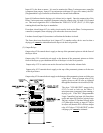
Input #14 indicates that the drying cycle is done (air jet signal). Once the output relay of the
Phase 5 microprocessor controller (computer) turns on contact relay #4, input #14 is turned
on. This in turn signals the PLC to illuminate the "END OF CYCLE" (E.O.C.) L.E.D. (light
emitting diode) until the dryer is attended to.
Front door closed (input #15) is a safety circuit used to lock out the Phase 5 microprocessor
controller (computer) from a drying cycle unless the doors are closed.
Lint door closed (input #16) monitors/verifies that the lint door is closed.
The front down/rear down/dryer level (input #17) is another safety device used so that a
drying cycle
cannot be initiated unless the dryer is in the level position.
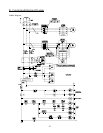
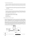
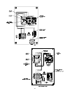
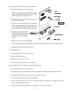
(2) Output Relays
Output relay #210 controls the air supply to the top of the pneumatic piston to tilt the front of
the dryer down.
Output relay #211 controls the air supply to the bottom of the pneumatic pistons to tilt the
front of the dryer up, provided that the rear of the dryer is in the level position.
Output relay #212 is used to turn on the fan and cool the load after a heater fault.
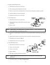
Output relay #213 controls the air supply to the top of the pneumatic pistons to tilt the rear
of the dryer down.
Output relay #214 controls the air supply to the bottom of the pneumatic pistons to tilt the rear
of the dryer. Rear up (output relay #214)
applies power to the S6 rear up solenoid
through the front down level switch (LS1B).
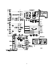
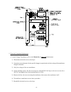
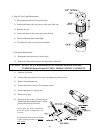
The dryer "CLEAR/STOP" output (relay
#215) is used to lock out the Phase 5
microprocessor (computer) from running a
drying cycle. If the PLC (Programmable
Logic Controller) has input #4 (front door
open) and input #10 (blower [squirrel cage
fan] on), or input #7 (lint door closed), input
#15 (front door closed), or input #17 (dryer
level) are off, then the PLC will close output
relay #215 (dryer "CLEAR/STOP") so that
a drying cycle cannot be initiated.


Find Your Products By Category
Please Login
