
4.3
Owner's of the ADC Clothes Dryer AD-310 gave it a score of 4.3 out of 5. Here's how the scores stacked up:

88
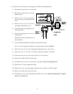
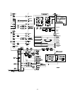
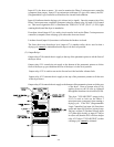
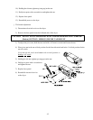
b. PLC (Programmable Logic Controller)
1) The PLC (Programmable Logic Controller) can consist of one (1) or two (2) modules; a main module
and in some cases an expansion module is used for additional inputs and outputs.
NOTE: The information listed below is generic in nature, refer to blueprints for specific details.
a) The main PLC (Programmable Logic Controller) module has eight (8) input relays which are
labeled #0 through #7 and six (6) output relays labeled #200 through #205.
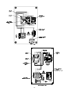
(1) Input Relays
Input relays #0, #1, #2, and #3 are set up as users inputs to signal what specific function is to
be performed (i.e., open-close door, load-unload tilted, open doors, and level dryer). These
input relays are charted as 1 and 0 (
1 is logic on and 0 is logic off). When either an input
relay or an output relay in on, the appropriate L.E.D. (light emitting diode) on the PLC will be
illuminated.
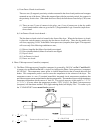
For input relay #4 to turn on, the left and right front doors must be completely open. Once
these doors are completely open, the jog forward (input #5) and jog reverse (input #6) can turn
on through the PLC which in turn rotates the tumbler (drum and basket) through either output
relay #204 or output relay #205 providing the lint door is closed. This interlock is performed
through PLC input #16 (lint door closed), or in some cases contactor B is used to interrupt the
24 VAC signal from reaching the drive contactors and the tilting solenoids. Rear door open
(input relay #7) is used on 2 door dryer models to verify rear door status.
(2) Output Relays
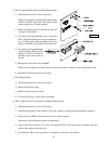
Output relay #200 controls the open front door function. When this signal is energized, the
pneumatic valve opens allowing air into the two (2) door cable cylinders, which in turn opens
the front doors.
Output relay #201 controls the open rear door function.
The end of cycle (E.O.C.) - output relay #202 - switches on after an air jet signal is received.
This output relay will stay illuminated until the dryer is attended to.
Output relay #203 is used to signal a heater fault.
Output relay #204 (drive forward) and output relay #205 (drive reverse) are used to perform
jog functions.
b) The expansion PLC (Programmable Logic Controller) module has eight (8) inputs which are
labeled #10 through #17 and an six (6) output relays labeled #210 through #215.
(1) Input Relays
A fan on or off signal (input #10) determines if the dryer is operating. If the dryer is operating,
the door function and tilt function shut down.
Input #11 is the heater fault reset. When the dryer is in a heater fault, an input (at input #11)
will reset the fault.


Find Your Products By Category
Please Login
