
2.7
Owner's of the ADC Clothes Dryer AD-200 gave it a score of 2.7 out of 5. Here's how the scores stacked up:

67
CAUTION: WHEN SERVICING THE HIGH VOLTAGE (HV) SECTION OF THE DRYER,
THE ELECTRICAL POWER MUST BE DISABLED. THE “EMERGENCY
STOP” (E-Stop) BUTTON DOES NOT DISABLE THE HIGH VOLTAGE TO
THE DRYER.
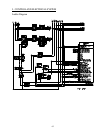
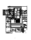
1. Control/Electrical System Description
a. 3-Phase (3ø) Electrical Power
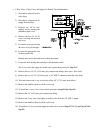
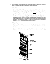
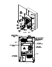
The 3-phase (3ø) electrical power for the dryer enters the dryer through the power distribution block
located in the dryer base electrical box. It is then distributed to the blower (squirrel cage fan) motor,
drive (basket/tumbler) motor, and transfer circuits.
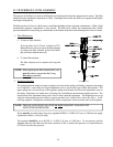
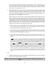
1) Blower (Squirrel Cage Fan) Motor
The blower (squirrel cage fan) motor circuit consists of a blower (squirrel cage fan) motor thermal
magnetic overload. The overload current is adjustable by a dial located on the face of the overload.
(Refer to the electrical specification diagram for correct current setting.)
Attached to the thermal magnetic starter (TMS) is an auxiliary contact used to sense an overload
trip. This produces a safety error so the dryer service is disabled (the dryer will not start).
In series with the thermal magnetic overload is the blower (squirrel cage fan) motor contactor. This
device enables the supply voltage to reach the blower (squirrel cage fan) motor. The blower (squirrel
cage fan) motor contactor is controlled by the Phase 7 microprocessor controller (computer). (Refer
to Section b-1 on page 69 for microprocessor controller [computer] information.) When 24 VAC
is applied to coil A1-A2, the contactor closes and enables the circuit.
The blower (squirrel cage fan) motor used for gas model dryers is 7-1/2 HP (5.6 kw) and for steam
model dryers is 15 HP (11.2 kw). The motor wiring configuration is dependent on the specific
voltage of the dryer. When wiring the motor, refer to the motor nameplate.
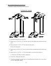
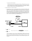
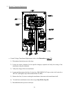
2) Drive (basket/tumbler) Motor
The drive (basket/tumbler) motor converts the 3-phase (3ø) power source entering the drive motor
thermal magnetic overload. The overload current is adjustable by a dial located on the face of the
overload. (Refer to the electrical specification diagram for correct current setting.) In this circuit,
the drive motor contactor follows the thermal magnetic overload.
The drive motor has two (2) separate sets of coils and two (2) separate sets of contacts. One (1) of
these sets is for forward basket (tumbler and drum) rotation and the other for reverse basket (tumbler
and drum) rotation. The thermal magnetic overloads and the contactors are located in the left hand
electrical cabinet. The direction of the drive motor is determined by the phases going into the motor
(i.e., in a reverse direction phase, L1 and L2 are switched). When viewing this contactor, the left
hand block connections are for the forward rotation direction (clockwise [CW]) when viewed from
the front of the dryer.
The drive (basket/tumbler) motor is a 3 HP (2.24 kw) motor. Refer to the motor nameplate for
specific terminal box wiring.


Find Your Products By Category
Please Login
